DEEP processing embeds class-leading compressors and processing emulations directly within the Input and Mix channels. An array of bespoke algorithms can be inserted on the fly without burning FX slots and without the setup, latency and licence hassles associated with external plug-ins.
The RackExtra FX and RackUltra FX portfolio combine the quality and wide choice offered by FX plugins with the convenience and low latency of onboard processing.
DEEP Processing Preamp models
Dual-Stage Valve
Inspired by a known studio preamplifier, this model recreates the distortion characteristics of valve circuits, from very subtle coloration to full overdrive. It can be fully bypassed with the On/Off switch.
Stage-1 adds subtle tonal harmonic distortion and offers two modes which mirror the typical valve topologies of analogue preamplifiers: Triode is richer in even order distortion resulting in a musical, warm response; Pentode is stronger in odd order distortion (predominantly 3rd), resulting in crisper, sharper sound.
Stage-2 provides overdriven valve emulation. It can be switched off circuit or to either Triode or Pentode mode. Bias controls the level of overdrive. With HiDrive Off, it produces pronounced ‘break up’ distortion and compression at high levels. HiDrive changes the gain structure to produce a continuous overdrive effect.
The HF control adjusts the HF content to compensate for mid-range tonal lift and high frequency compression.
The Output level is effectively a make-up gain to compensate for the level loss.
Tube Stage
Derived from our Dual-Stage Valve DEEP processor, this model recreates the distortion characteristics of valve circuits, from very subtle coloration to full overdrive, with a simplified control set. It can be fully bypassed with the On/Off switch.
A number of modes are available via the rotary selector switch offering different distortion characteristics – see the Dual-Stage Valve section for more information.
The Drive control adjusts the amount of distortion applied to the signal.
The Level control is effectively a make-up gain to compensate for the level loss.
DEEP Processing Compressor models
16T
Inspired by an industry classic VCA based RMS compressor this model produces a tight, punchy compression particularly useful with live bass and percussion and also vocals, and with a very easy to use three rotary control interface.
16VU
Based on an original vintage VCA based RMS compressor with VU needle meter, with pleasant characteristic sound due to its non-linearity and distortion artefacts, and also with a simple three rotary control interface.
Ducker
The Library for the Gate and Compressor processing blocks includes a channel Ducker with key source selection and LPF/HPF filters, plus controls of Threshold, Depth, Attack, Hold and Release.
Manual Peak
Offers the response of a peak based threshold detector with various smoothing, auto hold/recovery schemes to minimise distortion. The algorithm is capable of ultra fast attack time with minimal lag before onset.
Manual RMS
Offers the response of a fairly fast pre-threshold RMS detector with added ability to manually modify the post threshold ballistics for classic sounding RMS compression with additional attack or release smoothing.
Mighty Compressor
Inspired by a classic transistor array VCA dynamics processor, Mighty is an aggressive sounding compressor with a very fast attack. The Detector switch offers two distinct voices with easy control over Threshold and Release values in addition to an Output control to restore any volume lost.
The characteristics of Mighty make it particularly useful on kick, snare, bass and parallel compression duties.
Opto
Offers the response of a filament optical compressor. The release has non-linear exponential recovery, fast at the start and smooth for final recovery stage. This creates a smooth and musical sounding compressor.
OptTronik
Based on a legendary tube-driven, electro-optical compressor, OptTronik offers smooth, musical compression with easy-to-use controls. The Limit/Compress switch is used to set the compression ratio and amount of compression is determined by the Peak Reduction control. The Gain control can be used to restore any volume lost to compression. The Emphasis control is used to set the frequency response of the sidechain and offers variable or fixed preset settings.
Unit A and B offer two flavours based on two hardware units modelled.
Peak Limiter 76
A faithful emulation of the legendary FET limiting amplifier from the late 60s, complete with its nonlinear distortion characteristics, program-dependent Attack, Release and Ratio settings, and trademark ‘All buttons’ mode.
The Unit switch selects one of two units which have been modelled: the modern silver and the black vintage.
Gain Link engages “Rubber Band Mode”, whereby the Input and Output control will be linked and inverted. Increasing the Input will reduce the Output and vice-versa.
Bus
Inspired by a legendary VCA bus compressor, it delivers unrivalled sonic cohesion on LR and sub-mixes, with minimal pumping.
CompStortion
Emulating one of the most versatile compressors available with a huge range of Ratio Modes that subtly influence the Knee shape and the Attack and Release ballistics.
In addition to the numbered Ratio modes CompStortion also features Smash, a hard-knee brick wall Limiter and Brit which emulates the “All button in” behaviour of the 76 Peak Limiter with aggressive Attack and Release ballistics.
The Distortion modes go from least to most aggressive, with each one emphasising something slightly different.
Mode A Emphasises 2nd order Harmonic distortion.
Mode B A more aggressive version of Mode A at lower levels of Gain Reduction.
Mode C Emphasises 3rd order Harmonic distortion.
Mode D A more aggressive version of Mode C at lower levels of Gain Reduction.
The detector modes select which frequencies the Compressor’s detector is most sensitive to.
HP allows lower frequencies to pass without triggering the Compressor’s Detector.
Bandpass makes the compressor more sensitive to frequencies around 6kHz -7kHz
These options can also be used together.
DEEP Processing GEQ models
Constant-Q
Symmetrical cut/boost where the width (Q) of the filter is a constant 1/3rd octave for any amount of cut or boost.
Proportional-Q
Provides smooth wide Q for low cut/boost, which progressively tightens beyond 1/3rd octave for max boost/cut.
Digi-Q
Gain and width are optimised to minimise band interaction and to provide a frequency response as close to the slider positions as possible.
Hybrid
Allen & Heath have developed the best of both worlds. The boost is proportional-Q for smooth and warm small boost settings. The cut is Constant-Q providing clinical 1/3rd Octave attenuation with minimal band interaction.
DEEP Processing AMM
Operating Principles
The AMM works by automatically reducing the mix level proportional to the microphone activity at any time. It adds an automatic gain element and derives a trigger source within each assigned channel.
The AMM takes control by using its own post-fade gain element to make its automatic adjustments. It is typical to leave the faders at '0', but they can be adjusted if the engineer wishes to make additional post AMM level changes manually to adjust the relative balance between mics in the mix.
The AMM affects all channel post-fade sends but not pre-fade sends such as monitors.
The AMM determines when microphones are open (detects a level or speech) by analysing the channel signals at their pre-Insert point. The PEQ, Comp and fader do not affect AMM signal detection.
The AMM uses a complex algorithm to automatically optimise the overall gain by adjusting the microphone levels sent to the mix according to how many mics are open.
If just one mic is open then its level is passed through at 0dB and the others are attenuated. If several mics are open the overall gain is automatically reduced.
Additional features allow ambience to be maintained, crosstalk and false triggers to be eliminated, and microphones to be selected as 'Chair' to take priority over others by ducking their levels.
NOM Mode
NOM (Number of Open Mics) mode evolved from the AMM developed for the Allen & Heath IDR8 installed sound processor, NOM mode acts as a gate, turning an input on when a threshold is passed. The level adjustment for each open input is equal and depends on the number of microphones open and the NOM attenuation parameter which sets the amount of attenuation applied for every doubling of open microphones.
Adaptive Threshold - You do not need to set the open mic threshold. NOM mode senses the background ambient noise level and automatically adjusts the open threshold level to ensure consistent triggering regardless of background noise.
Ambience Maintenance - Keeps the last open microphone locked on until another channel is opened to ensure consistent ambient noise is maintained, especially important in a broadcast environment. If just one microphone is active in the AMM then it is held open to maintain ambience.
Scenes and the AMM
AMM settings are stored in dLive Scenes. However, these can be made globally safe from Scene recall using the Scenes / Global Safes screen in the Scenes menu. They can also be filtered out of individual Scene recall by highlighting a Scene in the list, touching its Recall Filter button to access its filter 'Others' tab and blocking the AMM item.
User Permissions and the AMM
AMM settings can be protected from selected users by disabling 'AMM' parameters in the MixRack / User Profiles / Set Permissions screen under the AMM tab.
Using the AMM
Set up and position the microphones. It is best to use the same type of microphone and position them so that the participants are not too close or too far from each. To avoid false triggering and phasing the distance from each voice to its mic should be closer than the distance between the mics. The distances from each mic to voice should be similar for consistent operation.
Set up an Audio or DCA Group for master control. Decide which mic channels to use for the AMM. Before assigning to the AMM we recommend you either route these via an audio Group to the LR mix (remember to also unassign these channels from the LR mix), or assign a DCA Group to them. This gives you a master fader and mute for quick overall control.
Set the mic gain and processing. It is best to start with the Group master fader down to avoid unexpected high levels in the PA while setting the gains. Use PAFL to check audio level and quality. Set gain for the loudest speech expected. Use the HPF and PEQ to tailor the sound for speech.
Set up the AMM. Use the Setup / Audio / AMM screen. This displays the current mode and assignments as well as blue bars showing the automatic gain settings. Touch the Setup button to choose NOM or D-Classic mode and adjust the available settings.
Assign the channels to the AMM. When you turn an assignment ON its fader will automatically move to its '0' position. The AMM takes over and keeps the mic closed until it picks up enough signal to trigger it.
Bring up the AMM in the mix. Turn one mic on by having someone talk into it. Raise the Group fader to set the required volume in the room.
RackExtra FX models
SMR Reverb
SMR Live is a Spatial Modelling Reverberator featuring 4 fully configurable complex spatial models Classic, Hall, Room and EMT. Each of these models use different reflection and decay algorithms to provide natural sound spaces ideal for Live sound.
Classic Emulates high quality plates. Shape tailors the reflection pattern. Min position for fast attack, mid position for rounded early reflections, and max position for separated early and late reflection patterns. Adjusting shape/size/predelay with decay can result in some great Hall reverbs. Small size settings not very useful in live sound applications.
Hall Emulates a real Hall reflection model. No shape control, reflections are controlled with Size, Source diffusion and Ref detail with rich deep decay spectrum.
Room Accurately emulates a characteristic complex room reflection pattern.
EMT Classic plate emulation. A great plate with good tonal balance for live use. Decay setting around 2 seconds is typical.
The SMR primary controls essential for live mixing are always visible:
LF Cut - 0 to 400Hz, 24dB/octave high pass filter to cut low frequencies of the input signal to the reverb.
HF Cut - 2kHz to 20kHz, 24dB/octave low pass filter to cut high frequencies of the input signal to the reverb.
Predelay - The time it takes before the reverb reflections and decay are heard.
Decay Time - Broad spectrum decay control. The time it takes for the reflections to decay to 60dB below the level of the direct sound is known as the RT60, an important measurement of reverb in a room.
HF Decay - Frequency at which the high frequency decay attenuation starts.
HF Slope - The attenuation slope of the high frequency decay. HF Decay and Slope are both essential for high frequency decay spectrum adjustment in a live space. Setting HF Decay and Slope low creates a natural sounding decay. Setting HF Decay and Slope high creates a dramatic decay.
In addition there are 5 pages of scrollable ‘Expert’ pages for the Reverb which allow precision control:
Page 1 - Reflections - Source Diffusion, Size, Shape, Ref Detail.
Dedicated to reflection control. Keep source diffusion and detail low to help intelligibility. Small sizes are not typical for live applications. ‘Shape’ is only available in the Plate model.
Page 2 - Echoes - Echo1, Echo1 level, Echo2, Echo2 level.
Dedicated page for user defined echo reflections. You can insert main reflections to create Echo reverb sounds. Echo1 goes to left Echo 2 goes right. Echoes may be layered over the reverb.
Page 3 - Decay Texture - Body Diffusion, Tail diffusion, Mod depth, Mod speed.
Separate body and tail diffusion controls can help prevent metallic decay through too much diffusion. Modulation depth and speed increase reverb density and add chorusing, effective on percussive program but not as useful on piano and vocal.
Page 4 - Decay Spectrum - LF decay, LF XOver, Colour, Colour Freq.
Separate LF decay control with crossover frequency and decay time, useful for live work. Colour is a tuneable element in the decay. High Freq colour settings can enhance ambience, although it can sound metallic with some programme.
Page 5 - Reflection/decay level - Reflection level, decay level.
These controls are dedicated to balancing reflection and decay to improve intelligibility.
Preset Name is displayed in the simulated LCD window. Touch and scroll using the screen Rotary for live update. This is a way of live auditioning all library presets for this module (factory, user and USB). You can also select and recall a particular preset using the Library window.
Stereo Tap Delay
Provides a clean digital delay with a maximum delay time of 2.7 seconds. One of the key features of the stereo tap delay is the ability to synchronise the delay times to note intervals based on the effects beats per minute value. The delay has two modes of operation:
BPM mode -Delay time is determined by the selected beats per minute and corresponding note value. Standard, dotted and triplet intervals are selectable via the interval selection wheel from whole to 16th intervals.
MS mode - Delay time is set directly in milliseconds. The unit offers control over input and feedback filters, delay width and switchable Scatter/Ping-Pong modes.
Note The Stereo Tap Delay can also be locked to the global tap tempo. Global rate can be manually entered or tapped in using the screen of any delay FX locked to global tap tempo, or by tapping a SoftKey assigned as Global Tap Tempo.
Input filter HP frequency – Sets the frequency of the high pass filter on the input to the delay. This cuts low frequencies.
Input filter LP frequency – Sets the frequency of the low pass filter on the input to the delay. This cuts high frequencies.
BPM / MS mode –Switches between Beats Per Minute and Milliseconds mode. In BPM mode the BPM and note selection wheels are displayed allowing delay times to be set as an interval of a selected BPM.
Interval Selection Wheel – Determines the delay time to be set in synchronisation with the chosen BPM. The values range from whole dotted intervals to 16th triplet notes. When an interval is not available due to the BPM being too low, the interval will grey out and not be selectable.
MS time window (in MS mode) – Allows the delay time to be set directly in milliseconds.
Link – Links the left and right delay times.
Local / Global Tap – Locks the delay time to the global tap tempo allowing global synchronisation across the console or locally to this effect unit.
Fractional / Notation display – Choose to display either fractions or notation representation of the selected interval on the selection wheel.
Feedback filter frequency – Selects the frequency of the filter in the feedback path of the delay unit.
Feedback filter slope – Selects the slope of the feedback filter. A larger slope provides greater feedback attenuation.
Scatter mode – Modifies the delay pattern between Ping-Pong and scattered. Scatter off creates classic Ping-Pong delays. Scatter on reconfigures the regen path giving one delay on the shortest side and regen on the longest side replacing Ping-Pong bounce with some interesting delay patterns. For example, an echo on one side and a regen echo pattern on the other.
Feedback – Controls the amount of the feedback in the delay. A larger amount increases the number of audible repeats.
Width – Controls the stereo imaging of the delay unit, from focussed mono sounding to panned wide stereo delays.
Preset Name is displayed. Touch and scroll using the screen Rotary for live update. This is a way of live auditioning all library presets for this module (factory, user and USB). You can also select and recall a particular preset using the Library window.
Bucket Brigade Delay
This is an emulation of a vintage analogue delay unit that used a 'bucket brigade device' (BBD) chip for the delay. This was a discrete analogue time delay line where the stored analogue signal was moved along a series of capacitance sections one step at each clock cycle, similar to a line of people passing buckets of water.
Unlike the analogue equivalent, the Bucket Brigade benefits from long delay lines (up to 2.7 seconds) but maintains the signal degradation expected from such a device. The level of signal degradation is switchable via a ‘DIST’ (distortion) control which switches between different nonlinearities in the feedback path. Note that even in its cleanest mode the Bucket Brigade delay will degrade and band limit the signal.
The delay has two modes of operation:
BPM mode - The delay interval is determined by the selected beats per minute and corresponding note value. Standard, dotted and triplet intervals are selectable via the interval selection wheel from whole to 16th intervals.
MS mode - The delay interval is set directly in milliseconds. The stereo beat delay can also be locked to the global tap tempo. There are controls for both input and feedback filters, with the latter having individual slope parameters.
Note The Bucket Brigade Delay can also be locked to the global tap tempo. Global rate can be manually entered or tapped in using the screen of any delay FX locked to global tap tempo, or by tapping a SoftKey assigned as Global Tap Tempo.
Input filter HP frequency – Sets the frequency of the high-pass filter on the input to the delay. This cuts low frequencies.
Input filter LP frequency – Sets the frequency of the low pass filter on the input to the delay. This cuts high frequencies.
Width – Controls the stereo imaging of the delay unit, from focussed mono sounding to panned wide stereo delays.
BPM/MS mode – Switches between Beats Per Minute and Milliseconds mode. In BPM mode the BPM and note selection wheels are displayed allowing delay times to be set as an interval of a selected BPM.
BPM window (in BPM mode)– Touch and use the rotary to select the BPM that the note values are synchronised from.
Interval Selection Wheel – Determines the delay time to be set in synchronisation with the chosen BPM. The values range from whole dotted intervals to 16th triplet notes. When an interval is not available due to the BPM being too low, the interval will grey out and not be selectable.
MS time window (in MS mode) – Allows the delay time to be set directly in milliseconds.
Link – Links the left and right delay times.
Local / Global Tap – Locks the delay time to the global tap tempo allowing global synchronisation across the console or locally to this effect unit.
Fractional / Notation display – Choose to display either fractions or notation representation of the selected interval on the selection wheel.
Low Damp Filter frequency – Selects the frequency of the low damp filter in the feedback path of the delay unit.
High Damp Filter frequency – Selects the frequency of the high damp filter in the feedback path of the delay unit.
Feedback filter slope – Selects the slope of the feedback filter. To filter more or less of the feedback path.
Feedback – Controls the amount of the feedback in the delay. A larger amount increases the number of audible repeats.
Dist – Changes the distortion characteristic of the feedback path allowing for more or less signal degradation.
Preset Name is displayed. Touch and scroll using the screen Rotary for live update. This is a way of live auditioning all library presets for this module (factory, user and USB). You can also select and recall a particular preset using the Library window.
2-Tap Delay
Separate left and right tap delay outputs from a mono’d input. Left and right delay can be dialled in using the screen Rotary, tapped on screen or tapped using a SoftKey. Individual tap indicators flash at the tap rate.
Note 2-Tap Delay is no longer available within the factory library from firmware V1.5 onwards as it is replaced by the newer Stereo Tap Delay.
The left and right delay taps can be ganged to mono using the Link button. There are adjustment controls below each delay tap for fine tuning the values.
The regen path (feedback) has a low pass damping filter. This filter has a frequency and a slope control for fine adjustment of loop delay HF attenuation. There is also a stereo output width control.
LF Cut - 20Hz to 8kHz HF Cut 400Hz to 20kHz These filters control the input spectrum. The 24dB/octave slope gives brick wall control on what signal spectrum gets delayed.
Delay range - 5ms to 1360ms Delay tap controls Left and Right are tappable, shown with flashing leds.
Fine delay Left and Right adjustment in 1ms steps.
Link sets Left and Right tap delays equal with one control.
Scatter modifies the delay pattern between Ping-Pong and scattered. Scatter off - creates classic Ping-Pong delays. Scatter in - reconfigures the regen path giving one delay on the shortest side and regen on the longest side replacing Ping-Pong bounce with some interesting delay patterns. For example, an echo on one side and a regen echo pattern on the other.
Feedback controls the regeneration of the delay, creating loop delays. Feedback filter controls HF attenuation in the regeneration path/loop delay. The frequency and slope controls give the engineer precise HF attenuation control in the delay loop. Slope set mid for typical settings. Slope minimum is a light HF attenuation setting, maximum position is a large HF attenuation setting.
Width controls the stereo width of the output. Min position = mono, max position = LR.
Preset Name is displayed. Touch and scroll using the screen Rotary for live update. This is a way of live auditioning all library presets for this module (factory, user and USB). You can also select and recall a particular preset using the Library window.
Echo
This emulates the classic tape echo. It faithfully models the many non-linear attributes of the original hardware. These include frequency warping as the repeat rate is adjusted (essentially changing the tape speed), non-linearity and harmonic content at extreme intensity levels, and various other idiosyncrasies associated with motor speed inaccuracies, tape drift and wow. The Echo also emulates saturation and high frequency characteristics of the record head on tape, found on the original hardware. The Echo allows for 7 different ‘modes’, each of which activates certain read heads on the tape. There are 3 read heads in total which are a fixed distance apart; by changing the repeat rate it is possible to vary the delay time at each of the heads. The shortest delays can be found with mode 1 and the longest with mode 3. Modes 4-7 are a combination of read heads which can lead to complex repeat patterns and a greater risk of instability. The Echo will accept stereo input however it only has a mono output.
Input Gain - Can boost or cut up to 15dB of gain on the echo input.
Noise – Turns the analogue noise emulation on or off.
Mode Selector – Switches between the ‘read heads’ of the tape machine allowing for different lengths of echo. 1-3 selects a single read head; 4 – 7 selects a combination of multiple heads for a multi layered echo.
Note Be aware that when multiple heads are selected there is a greater chance for instability and self-oscillation which can result in large output levels. For normal use it is advised to use modes 1-3 to prevent excessive feedback.
Bass – Can cut or boost low frequency content in the feedback path of the echo. The centre position provides a bypassed response.
Treble – Can cut or boost high frequency content in the feedback path of the echo. The centre position provides a bypassed response.
Repeat Rate – Controls the echo time by adjusting the artificial motor speed of the tape. A quicker rate means a shorter echo. For the longest echo select mode 3 and set the repeat rate to the far left.
Intensity - Controls the intensity of the feedback path in the echo. More intensity results in more repeats. When intensity is set beyond 75% the unit is capable of self-oscillation and with external input will grow and evolve, however this can result in loud output levels which need to be monitored. When multiple read heads are selected (modes 4-7) added intensity causes even more instability and care should be taken to avoid clipping.
Echo Volume - Allows for a cut or boost of 15dB of gain on the echo output.
Preset Name is displayed. Touch and scroll using the screen Rotary for live update. This is a way of live auditioning all library presets for this module (factory, user and USB). You can also select and recall a particular preset using the Library window.
Gated Verb
An accurate emulation of the classic 80’s Gated Reverb plus two other variants called ‘Panned’ and ‘Powerbox’. The user interface gives instant access to Lo-cut Hi-cut decay spectrum filters and the gate envelope controls - predelay, attack, hold and release.
We depart from the 80’s and provide a visual representation of the gate time domain envelope helping the engineer ‘see the time envelope of the gate’. Also included are mono, stereo and wide imaging options and decay diffusion control.
Lo cut Decay Filter - 20Hz – 6kHz, 24dB/octave Hi Pass Filter to control the decay spectrum.
Hi cut Decay Filter - 400Hz – 20kHz, 12dB/octave Low Pass Filter to control the decay spectrum.
Time domain Gate envelope controls:
Predelay - 0 - 170ms adjustable pre-delay of gate opening (prior to attack starting).
Attack - Time period for gate to open.
Hold - Time period that the gate remains fully open.
Release - Time period for gate closing.
Maximum gate open time (attack + hold + release) = 500ms.
Models:
Classic nonlinear - Emulates the faithful 80’s classic gated reverb.
Panner - Rapid panning between L and R in the reverb. Short time movement FX.
Powerbox - Max power in gated energy. Not as de-correlated as classic non-linear.
Mono/Stereo/Wide - Option to switch between mono, stereo and wide stereo field output.
Diffusion - Minimum diffusion for ‘clear’ low diffusion in the reverb decay. Maximum diffusion for ‘rich’ highly diffused reverb.
Preset Name is displayed. Touch and scroll using the screen Rotary for live update. This is a way of live auditioning all library presets for this module (factory, user and USB). You can also select and recall a particular preset using the Library window.
ADT Doubler
An Automatic Double Tracking module capable of creating short echo/chorusing, classic double tracking and ‘slapback’ tape delay loops.
The ADT is very effective in creating stereo double and quad tracked voices from a mono input. There is also a stereo width enhancer. The tracked voices can be auto panned in the stereo field. The ADT is perfect for creating classic doubling effects, thickening programme on stage or developing a stereo sound field without resorting to chorusing.
The module is stereo in, stereo out (with software normalised mono input if the source is mono). ADT will create a stereo field from a mono source.
Delay Separation - Min position for short delay separation producing Chorusing with Thickness set high. Mid position for classic doubling. ¾ position with thickness high for echo-chorusing. Max position with low thickness for tape loop and slapback Echo.
Thickness - Creates flutter modulation in delay voices. Very high settings can smear detail on some programme.
Double/Quad Track - Clear double tracking in the first position. Switch across for thicker quad tracking. With some programme Quad can get too thick and smear detail.
Wide - Extends the delay separation differences between Left and Right enhancing the stereo image.
Autopan - Automatically pans the chorus voices (wet signal only, not the dry signal). This is level modulation of the wet effect (not the dry signal) across the stereo field. It is not complete signal auto panning.
Depth - Determines the amount of movement across the stereo field. Use higher settings for a stronger effect.
Speed - Determines the speed of movement across the stereo field.
Preset Name is displayed. Touch and scroll using the screen Rotary for live update. This is a way of live auditioning all library presets for this module (factory, user and USB). You can also select and recall a particular preset using the Library window.
Chorus
Chorus derives from the late 80’s where different stereo field creation techniques influenced the sound of each chorusing unit.
Chorus recreates the classics using 3 stereo-field emulations. These emulations can be switched in any combination creating many different stereo fields. All switches up gives no stereo enhancement.
The traditional Rate and Depth controls cover the centre panel. The LFO driving the modulator can be switched to sine or rectified shape. The auto-panning section pans the chorus voices giving stereo level shimmer, another classic modulator effect.
The module is stereo in, stereo out (with software normalised mono input if the source is mono).
Stereo Field emulations - All switches up turns all stereo enhancement off. There are 3 stereo field emulations each active with switch down. These create stereo fields from a mono input. The 3 emulation switches can be used in conjunction with each other creating many different stereo field sounds, just like a number of classic chorus effects. Be careful as all 3 selected together can sound muffled rather than more ‘stereo’ with certain programme.
LFO Split uses two separate LFO’s for left and right, creating a rich stereo image that varies with rate.
Wide pushes the left and right voices apart producing a very wide stereo image, but can sound phasey on some programme.
MultiVoice stereo field is created through multi-voice splits across left and right. It typically produces a thick stereo sound, but can sound muffled on some programme.
Rate - Min position for slow speed, best used with high depth settings for slow, deep chorus. Mid position for medium speed. Use with mid depth for classic chorus sounds. Max position for fast speed. Use with low depth settings for lively chorus.
Depth - Min position for small voice pitch variation. Useful with fast rates. Max position for large voice pitch variation. Can cause audible pitch change. Best with slow rate.
Sine/Rectified - modulator Switches between sine wave and rectified LFO modulator.
Autopan - Automatically pans the chorus voices (wet signal only, not the dry signal). This is level modulation of the wet effect (not the dry signal) across the stereo field. It is not complete signal auto panning.
Pan Depth - Determines the amount of movement across the stereo field. Use higher settings for a stronger effect.
Speed - Determines the speed of movement across the stereo field.
Preset Name is displayed. Touch and scroll using the screen Rotary for live update. This is a way of live auditioning all library presets for this module (factory, user and USB). You can also select and recall a particular preset using the Library window.
Symphonic Chorus
A faithful emulation of the 80’s classic chorus effect. Simple to use and frequently requested. The unit has just two controls, Frequency and Depth, controlling the rate and delay range of the stereo modulator. The unit produces a rich, lively and wide chorus sound with a suggestion of very mild phasing / flanging.
Live engineers commonly use this unit for thickening vocals and strings and creating a spatial sound from a mono source. This has led to two factory presets ‘SymphonicVox’ and ‘SymphonyStrings’.
The module is stereo in, stereo out (with software normalised mono input if the source is mono).
Frequency - Adjusts the modulator speed. Minimum setting is a very slow modulation. Maximum is fast modulation. Like the original 80’s unit, the maximum frequency setting is extreme and should be used with shorter depth settings to avoid space ship sound effects. Typical settings are just left of mid position.
Depth - Adjusts the modulator delay depth. Minimum position is short delay depth producing subtle modulation. Some programme may be more prone to phasing/flange type sounds. Mid position is a typical delay depth setting creating tonal depth with rich chorusing. High settings of depth can sound extreme if the frequency is also set too high. Mid position is a typical starting point.
Preset Name is displayed. Touch and scroll using the screen Rotary for live update. This is a way of live auditioning all library presets for this module (factory, user and USB). You can also select and recall a particular preset using the Library window.
Flanger
Three classic flanger effect emulations – ‘Ambient’, ‘Vintage’ and ‘Wild’. During research of classic pedal flangers we found numerous LFO modulators and stereo splitting techniques. We implemented them all.
For classic deep flange set Stereo Split and Stereo Spread off, pick triangular modulation, Vintage type and adjust Depth and Regeneration. The Manual switch overrides the LFO, for manual flange sweeps, only found on few historic flangers.
The module is stereo in, stereo out (with software normalised mono input if the source is mono).
Stereo Split Uses two separate LFO’s for left and right, creating an enhanced stereo image with left and right flanging in different directions. Can sound very ‘psychedelic’. Enhanced Stereo Split can reduce the intensity of the flange zone.
Stereo Spread Creates an enhanced stereo image by offsetting left and right flange voices with dynamic delay. Can sound super wide stereo or phasey depending on programme. Enhanced Stereo Spread can reduce the intensity of the flange zone. With both Stereo Split and Spread off the stereo image is preserved. For classic deep traditional flange effect turn both Stereo Split and Spread off.
LFO Type selector:
Manual Speed control becomes a manual sweep control (LED goes green). Sine, Rectified sine, Inverted rectified sine, Triangular Shape of auto oscillation. Speed Ranges from off to fast modulation. The LED goes red when in auto mode, green when in Manual mode.
Depth - Adjusts the flange zone depth. Min position operates in a tight flange zone. At max position the effect sweeps in and out of the flange zone creating a greater tonal change. High settings of Depth can sound extreme.
Regenerate - Produces feedback into the flanging delay line, making the flange more pronounced. Min position can result in no audible flange. Max position can sound too aggressive.
Emulation Types:
Ambient - HF rich, subtle flange, creating ambience. Great with overhead mics for a spatial sound.
Vintage - Creates a classic silky sound reminiscent of tape machine flanging. Regen control is well balanced LF and HF and the flanging does not get too aggressive.
Wild - An untameable, dramatic effect. The sound turns inside out.
Preset Name is displayed. Touch and scroll using the screen Rotary for live update. This is a way of live auditioning all library presets for this module (factory, user and USB). You can also select and recall a particular preset using the Library window.
MOO 12 Stage Phaser
A classic 12 stage emulation producing rich textured phasing with plenty of control. The user has control of number of stages, feed forward and feed back, and ‘zero’ depth manual mode – to manually sweep the Phaser using the offset control.
The classic characteristic sound is produced by careful emulation of the phase chain and operating frequency range around the offset control. Equally important is the emulation of harmonic signatures produced by the companded analogue delay lines producing rich harmonics adding thickness to the sound. The split/mono LFO switch toggles between in-phase intense phasing and split-phase mode - creating spatial rotary effects.
There are many different possibilities through varying the number of stages in the phase chain output or the feedback resonance path. Setup depends on the instrument applied to the unit. Lower numbers produce clean thin sounds. A higher numbers of stages produce a richer phasing sound.
Phasing Stages - Selects which point in the phase chain is taken as output. 6 stages produce a clean phase. However the classic rich sound is 12 stages.
Resonant Stages - Select which point of the phase chain is taken into the feedback ‘mix resonance’ circuit. 12 Stages is classic.
Mix Resonance - Controls the amount of feedback into the phase chain input. Classic sound around 5 - 8. Full resonance at 10.
LFO Rate - Variable between 0.1 to 10Hz
LFO Select switch - Sine / Rectified / Inverse Rectified / Linear(Triangular) are selectable. Classic unit uses Linear(Triangular). Slow Phasing sounds great with Sine. Rectified variants can create notches or phase spikes which can sound cool. Rectified variants are twice the speed.
LFO split switch ‘Mono’ setting configures the Left and Right Phase Chains to modulate in phase, the strongest effect. ‘Split Phase’ runs Left and Right not in Phase, creating a stereo swirl for added spatial rotary effect.
Depth - Controls the amount or depth of LFO modulation in the phase chain. Extreme settings can sound unnatural. Setting this control to minimum turns the LFO modulator off and relies on manual sweeping of the phase chain using the ‘offset’ control.
Offset - Shifts the operating frequency range of the Phaser. Maximum settings force the Phaser to operate in higher frequencies. Lower Offset settings allow lower frequency phase sweeps (more intense). In manual mode (Depth = 0) the user can adjust the phase sound with this control.
Preset Name is displayed. Touch and scroll using the screen Rotary for live update. This is a way of live auditioning all library presets for this module (factory, user and USB). You can also select and recall a particular preset using the Library window.
Hypabass
A sub-harmonic synthesis unit used in the live sound environment to generate infra and sub bass spectrum from weaker bass programme. We initially emulated the American analog classic, but implementation in DSP gave us the ability to use more sophisticated techniques in the sub harmonic generator and filtering stages. The result is reduced distortion in the infra bass section and much better independent control of the infra and sub bass spectrum, essential for live PA use.
The module is stereo in stereo out (with software normalised mono input if source is mono). The stereo signal remains stereo throughout the signal path. There is no mono’ing to produce either the infra or sub bass path.
• BEWARE - Extreme care is needed. Driving high infra bass levels into insufficient speakers may lead to speaker equipment damage.
Operation
‘Hypabass’ is a sub harmonic synthesis module. An LF input de-emphasis/emphasis trim stage feeds the sub harmonic generator creating low distortion, low frequency spectrum below the source input spectrum. This sub harmonic spectrum is then band-split into Infra Bass (18-36Hz) and Sub Bass (36 Hz upwards). This allows Infra and Sub bass to have separate level controls, essential for controlling ‘Infra Bass’ and ‘Sub Bass’ preventing speaker equipment damage, and dealing with resonant acoustics or speaker resonance with exotic LF cabinet porting. Separate Infra Bass and Sub Bass meters are provided. Each are peak detected from both Left and Right signal paths and presented on one meter.
UPPER FREQ CUT - Controls the upper bandwidth of the sub bass harmonic spectrum. This setting depends greatly on the sub bass speaker equipment and the original bass content. Typically a low setting is common to prevent the generated sub bass upper harmonics clashing with the original bass content. Beyond mid position is only useful for Lost Fundamental mode.
LF INPUT BOOST - This filter stage provides emphasis on the input spectrum into the sub harmonic generator and can be used as a global ‘more or less’ control once everything else is setup.
INFRA BASS Mode - This is the default mode. Energy in the Infra and Sub bass spectral regions is synthesised from the input bass content. Using the independent level controls the engineer can balance Infra and Sub bass.
• Avoid infra bass damaging equipment or sub bass resonating. UPPER FREQ CUT needs to be kept low to prevent the generated sub bass upper harmonics clashing with the original bass content.
LOST FUNDAMENTAL Mode - These harmonics can be output to a mid-range driver to create apparent bass energy since these upper harmonics are musically related to the original bass content. Useful for increasing bass perception in music driving mid-range speaker systems. This turns the Infra bass section off and modifies the output spectrum to operate in the typical upper bass region. Using the Sub level and UPPER FREQ CUT the engineer can manipulate the output to contain harmonics that are above the input bass spectrum.
Preset Name is displayed. Touch and scroll using the screen Rotary for live update. This is a way of live auditioning all library presets for this module (factory, user and USB). You can also select and recall a particular preset using the Library window.
De-Esser
Based on the flagship iLive FX engine, the De-Esser emulates the classic Auto-Threshold circuit commonly found on high end hardware units. This produces a constant sibilance reduction regardless of signal level, resulting in a more natural De-Essing process. In comparison, threshold based De-Essing produces inconsistent reduction activity which can result in unnatural vocals.
De-Esser features an adjustable frequency point and a Listen button to allow monitoring of the sibilant region. The response of the De-Esser and the amount of reduction applied are adjustable to suit vocal programme. Three filter types are available: the Classic industry standard most effective with sibilance in the 3k to 6k range, Shelf for reduction around and above the selected frequency, and Band Pass, most effective when sibilance is in the 5k to 8k range.
The two channels are independent but their controls can be linked thanks to a latch switch.
Listen - A momentary switch used to monitor the left or right channel to listen to the ‘ess’ band to which the gain reduction will be applied. The Listen button is independent of the “Link” configuration so that even when Link is set, the left Listen monitors the left channel and the right Listen monitors the right channel.
Frequency - Adjusts the lower boundary of the region thought to contain sibilance. This will typically be around the 6kHz range. Adjust the value to capture the “ess” heard on the channel. The frequency is adjustable from 3kHz to 8kHz. Like many advanced De-Essers this is not a simple notch filter. Typically you need to set the frequency slightly lower than the centre frequency of the ‘ess’.
Reduction - Provides control over the amount of gain reduction applied to the selected frequency band. At “Min”, the De-Esser will not attenuate the band. At “Max” the De-Esser will attenuate the band by up to 24dB.
Response - Adjusts the speed with which the De-esser responds to the presence of ess/sibilance. Medium setting corresponds to the speed found on the iLive platform. Fast setting is much faster, and Slow is roughly half the response time of iLive. To avoid slight artefacts in vocal programme try using the Slow or Medium settings.
Link - Forces the left and right De-esser channels to be matched. If the two channels have different, non-zero settings and the link control is activated, the right channel settings will be set to match those of the left channel. If the link control is then de-activated, the right channel will then reassume the settings it had before the link was initially activated.
Preset Name is displayed. Touch and scroll using the screen Rotary for live update. This is a way of live auditioning all library presets for this module (factory, user and USB). You can also select and recall a particular preset using the Library window.
Rotator
The Rotator is a model of a traditional rotary speaker cabinet such as those used to create the familiar Leslie organ sound. It simulates the rotating horn (treble) and woofer (bass) along with their crossovers.
Rotors – Turns the treble/woofer motors on/off. When the motors are off, the speakers are both facing the front of the unit. When switched on, the motors will ramp up to the speed indicated by the Speed control. The woofer motor accelerates more slowly than the treble motor. When switched off, the motors will then decelerate to the minimum speed, until stationary and facing the front of the unit. The On/Off switch controls only the rotor speed, not the whole effect.
Speed - Controls the speed of speaker rotation. Its lower setting is 0.1Hz (10 revolutions per second). The other two marked positions emulate those provided on classic rotary speakers: Chorale (indicated as “chor”) and Tremolo (indicated as “trem”). The big lamp flashes to show the treble speaker speed.
Width - Adjusts the stereo width of the two microphone outputs, and therefore the spatial “depth” of the effect. At the “Mono” setting both simulated microphone outputs are summed equally to the left and right outputs. At the L/R setting the simulated left/right microphone outputs are sent to the left / right output channels correspondingly.
Balance - Adjusts the relative weighting of the treble/woofer speakers. At the “LF” setting, only the output of the woofer is heard. At the “HF” setting, only the output of the treble horn is heard. You can balance between the two.
Deflectors - Simulates the attachment (On) or removal (Off) of the deflectors on the end of the treble horn.
Back Panel - Simulates the attachment (On) or removal (Off) of the cabinet back panel. This changes the simulated cabinet response as appropriate.
Mic Select - Allow for configuration of the two simulated microphone positions - Side-Side (microphones on opposite sides of the cabinet), Front-Back (mics at front/back of the cabinet), Front-Front (both microphones at the front of the rotary speaker). In Front-Front mode, the “Separation” rotary becomes available. This allows for the distance between the two front-positioned microphones to be adjusted.
Tube Drive - Controls the tube (valve) drive simulation. With the control at “On” the tube drive is active. With the control at “Off”, the tube drive is completely bypassed. The tube drive rotary control adjusts the depth of the distortion (1 = slightly warm, 11 = distorting).
Mains Hum Panel - Adjusts the level of simulated mains hum introduced.
50/60 - Switches between mains frequencies typical to the UK (50Hz) or US (60Hz).
VS1 Vocal Shift
VocalShift VS1 is a stereo vocal pitch shifter squeezing two channels of high quality pitch shifting into a single effect. It has a very low latency (<6ms), covers the whole vocal frequency range, and minimises the phasing and flutter artefacts common with many pitch shifters.
VocalShift allows large shifts of up to +/- 1 octave, with a further switchable octave downshift. The wide range makes it ideal for theatrical or more extreme musical effects. The left and right channels are fully independent, allowing separate, high quality pitch shifting on each.
The two channels can be linked and reset to flat (zero shift) using single button presses.
Semitones - Sets the amount of pitch shift applied to each channel in semitones. The range is -12 (one octave downshift) to +12 (one octave upshift). The current value is displayed in the centre of the rotary. When ‘active’, the control glows yellow/orange. In Link mode, both corresponding rotaries on the left and right channels will be illuminated. A change to either will then be reflected in both.
Cents - Sets the amount of pitch shift in cents (100 cents = 1 semitone). This is added to the setting of the Semitones (and oct down switch) control to give the overall shift (+1 semitone and +50 cents = +150 cents pitch shift). The cents control is useful for providing very small pitch shifts, for example for phasing and doubling effects.
Oct Down Switch - Provides an additional 1 octave downshift to the current pitch shift settings (i.e. +12 semitones and -1 octave = no overall shift).
Flat - Sets all pitch shift controls to zero (Semitones, Cents and Oct Down are all set to zero).
Width - Controls the stereo width of the two pitch shifted voices, and therefore the weighting of each in the left/right output channels. At the “Mono” position, the left and right channels are mixed equally to both left and right channels resulting in a centre pan, mono effect. At the “L/R” position, the left voice is fed only to the left channel and the right voice to the right channel. Other positions graduate between the two.
Link - Forces the left and right voices to be matched. If the two channels have different, non-zero settings the right channel pitch shift settings will be set to match those of the left channel. If the link control is then turned off, the right channel will restore its settings from before the link was turned on. The Link control links the Semitones, Cents and Oct-Down control. Pressing either “Flat” switch when Linked results in both voices being set to zero.
Preset Name is displayed. Touch and scroll using the screen Rotary for live update. This is a way of live auditioning all library presets for this module (factory, user and USB). You can also select and recall a particular preset using the Library window.
Pitch Doubler
PitchDoubler is a stereo, pitch shifting doubler effect generating the effect of additional voices from its input. It is based on the same pitch shifting technology as VocalShift, with the associated low latency (<6ms), wide frequency range (down to around 80Hz) and minimal phasing / flutter artefacts. The effect squeezes two channels of high quality pitch shifting into a single effect slot, along with further features such as adjustable delay and modulation.
The PitchDoubler has completely independent left and right channels, which can be mixed to the left/right outputs of the effect by means of the stereo width control.
The doubling effect is achieved by provision of time delay, and modulated pitch shift. Sliders are provided on each channel for independent control of the delay (0 – 25ms) and the pitch shift (-100 -> +100). A pitch modulation LFO module, with adjustable rate and depth, provides a natural variation in the pitch shift.
Delay - Sets the amount of delay applied to each voice. It is adjustable from 0 to 25ms. A readout of the delay value is provided below the fader.
Pitch - Sets the amount of pitch shift provided, varying from -100 cents (= 1 semitone) at the lower position to +100 cents at the upper position. The centre position corresponds to zero pitch shift. A readout of the current pitch shift value is provided below the fader.
Width - Controls the stereo width of the two voices. At the “Mono” position, the left and right channels are mixed equally to both left and right channels resulting in a centre pan, mono effect. At the “L/R” position, the left voice is fed only to the left channel and the right voice to the right channel.
Level - Provides attenuation for each voice in the doubler. A level of 0dB will pass the voice without any attenuation. A level of -6dB will pass the voice at half volume, and -Inf will zero the output. A readout of the current gain value is provided to the bottom left of the rotary.
Pitch Mod Panel
Active - This panel presents controls for applying LFO (low frequency) modulation to the pitch shift setting. Make sure the “Active” switch is turned on.
Rate - Controls the rate (frequency) of the LFO applied to the pitch shift. The rate is adjustable from 0.1Hz to 10Hz.
Depth - Controls the depth of modulation applied to the pitch shift. Full depth (100) means that the pitch shift is modulated by the full amount of its current setting. If depth is 0, no pitch modulation is applied.
Dynamic EQ
DynEQ4 is a model of the industry standard stereo 4-band Dynamic Equaliser. It is an advanced processing tool providing four bands of equalisation that respond to the dynamics of the signal.
The Dynamic EQ can be loaded into one or more of the FX slots and then inserted into any of the input or mix channels.
Main Graph - Displays the 4 band frequency response, with the shaded fills showing dynamic activity and the solid outline showing maximum cut/boost for each band. Bands grey out if they are bypassed.
Thresh View - Primary control panel with main cut/boost and dynamics controls for each band. You can drag the points in the graph to adjust frequency in this mode.
Comp/Exp - Sets the maximum amount of compression (EQ cut) or expansion (EQ boost) for the band when the sidechain signal level is ‘Above’ or ‘Below’ the threshold setting. Centre position is zero dB flat.
Above/Below - Selects whether the EQ operates when the signal is above or below the threshold.
Threshold (-50dBu to 18dBu) - Sets the level at which the sidechain GR cut or boost occurs for that band. A threshold dependent ‘zoom’ meter is displayed.
Horizontal Gain meter - Shows Dynamic metering of Cut (green) and Boost (red).
Choose one of two Attack/Release modes:
• Std9 – standard, smooth frequency conscious release.
• Fast9 – has a fast release.
Filter View - For setting up the frequency response for each band.
Frequency control - All 4 bands are full range 40Hz - 18kHz.
Width control - LF and HF become shelving at the widest setting.
• Band1: LF Shelf, Bell 2.1–1/9 octave
• Band2: Bell 2.25–1/9 octave
• Band3: Bell 2.25–1/9 octave
• Band4: HF Shelf, Bell 2.1–1/9 octave
Listen - Touch to momentarily listen to the sidechain filter signal using the PAFL bus.
SC Config - Left and Right signals are summed to produce a mono sidechain for each band. Choose one of two modes:
- Cascade - The sidechain for each band is fed from the previous band. Each band is affected by the previous band activity.
- Parallel - All sidechains are fed from the input to the DynEQ. Avoids band interaction.
Bypass - Individual bands or the whole EQ can be switched in or out. The curve and controls grey out when the band is bypassed.
Master Trim and Meter - Lets you adjust the output +/-12dB to compensate for the effect of the EQ on overall level. The meter displays the stereo output signal.
Multiband Compressor
Two multiband compressor types provide independent compression control over different frequency bands. This is an advanced mixing tool for mastering and live sound control. It gives more precise control over the dynamics and less pumping effect than the more common single band compressor.
The Multiband Compressor can be loaded into one or more of the FX slots and then inserted into any of the input or mix channels.
Main Graph - A WYSIWYG graph displays the resulting crossover frequency response. Shaded red fills show dynamic gain reduction. The yellow curve shows makeup gain for each band, and the grey curve shows maximum potential gain reduction. Bands grey out if they are bypassed.
Slope - Choose the crossover slope - 6, 18, or 24 dB/octave. Slope 6 works well with the 3-band compressor. It has minimal phase summing distortion and sounds smooth. It is typically used for programme mastering. Slope 18 and 24 provide more band isolation and work well with the 4-band compressor for vocal and instrument control.
Attack/Release modes - There are two manual and 4 automatic dynamics modes:
• Peak Manual
• RMS Manual
• Auto Punch
• Auto Opto
• Slow AutoF
• Fast AutoF
Knee - Hard or Soft (easy knee model).
Link and Relative modes:
There are three operating modes with two buttons at the top right of the screen:
- Normal - Link and Rel buttons turned off. Independent control of each band.
- Link - All band parameters linked for quick setup.
- Relative - All band parameters linked for changes relative to settings made before the Rel button was turned on.
Per band controls:
Ratio - 1:1 (no compression) to 20:1 (maximum compression)
Gain - -6dB to +18dB
Threshold (-50dBu to 18dBu) - Sets the level at which the sidechain gain reduction occurs for that band. A threshold dependent ‘zoom’ meter is displayed.
In/Out - Individual band bypass. The curve and controls grey out for the band.
PFL - Momentary listen to the band solo’d to PAFL. Silences the other bands.
Sidechain Meter - Shows sidechain signal level and threshold point.
Bypass - Switches the whole compressor in or out. The curve and all band controls grey out when the compressor is bypassed.
Master Trim and Meter - Lets you adjust the output +/-12dB to compensate for the effect of the EQ on overall level. The meter displays the stereo output signal.
Transient Controller
This is an accurate model of the industry standard Transient Signal Processor.
Transient Signal Processors provide cut and boost of the attack and sustain envelopes of the input signal. This gives the sound engineer greater control over the transient behaviour of audio programme. The processor is auto-threshold which boosts or cuts specific parts of a signal envelope using auto attack and release times thus making control very simple. The unit has two independent linkable channels of processing, each with pre-gain and post-gain make-up and two optimised modes of operation.
Controls:
Attack – Sets the amount of gain applied to the attack portion of a transient. Allows up to 15dB boost or cut on the initial onset of a transient signal.
Sustain – Sets the amount of gain applied following a transient, boosting or cutting the sustain envelope of the signal. Allows up to 24dB of cut or boost. Changing the sustain gain on drums can help add or remove reverberation and can transform the tonal quality of the sound.
Pre Gain – Can boost or cut up to 15dB before processing.
Post Gain – Can boost or cut up to 15dB after processing.
In – switches the processor in and out. These are independent controls for each channel. The user interface greys out when the processor channel is out.
Metering – The unit provides signal and peak LED indicators for both input and output. The signal LED has three stages: Green for signal presence, yellow for nominal level above '0' and orange when approaching clipping.
Mode – The mode switch toggles between Transient and Continuous mode. If you hear unwanted artefacts then try changing the mode.
• Transient Mode - The default Transient Mode is designed to be used on percussive, transient material. Its automated attack and release reacts quickly meaning that even the sharpest of transients will be caught and processed with minimal distortion.
• Continuous Mode - Ideally suited for more steady state signals such as a bass or guitar. The unit responds much slower to transients and allows a smoother response.
Link – Links the two processing channels and changes the right channel parameters to match the left. When unlinked the right channel previous parameters are recalled. When linked, a common summed mono side chain is enabled for both channel 1 and 2.
Dimension Chorus
A model of a classic chorus device based on bucket-brigade technology. The 4 modes offer varying degrees of density from subtle spatial chorus to heavy modulation, with mode ‘E’ extending beyond the capabilities of the original outboard unit.
Controls:
Mode - Mode 1 is the subtlest, producing the most natural of voices and a small stereo spread. Mode 2 increases the width of the voices. Mode 3 increases both the modulation speed and depth of the chorus giving a thicker sound. Mode 4 is the most extreme and it expands the voices to be both louder, faster and wider. Expanding on the original device, we have included mode ‘E’ which follows the progression of more intense chorusing. This produces quite an aggressive chorusing mode but still utilises the unit’s voice architecture.
Output – Set to Wet Only when using in a Send/Return configuration, or Dry+Wet when inserted on a channel, with the wet/dry control for that channel set to fully wet.
RackUltra FX models
The following FX models may be loaded into the 8 RackUltra FX engines on dLive MixRacks fitted with the RackUltra FX card.
Spaces Reverb Designer
Capable of accurately reproducing the reverberation patterns of several different types of real environments.
The FX model controls are split across multiple tabs, with the Primary Controls and Quick Setup options being found on the Home Tab. Choosing an option from any of the Quick Setup dropdown menus will automatically configure the settings on the corresponding tab.
The Quick Setup option will turn grey when the settings have been subsequently changed from the Quick Setup preset.
Output EQ controls are also duplicated on the Home Tab. These are the same controls which can be found under the Output section of the EQ Tab.
Pre Delay sets the Delay of the Dry signal entering the Reverb Engine (0-170ms).
Decay sets the total Decay time for the Reverb Engine (0.1s – 60s+)
The Space Tab is where controls for the Reflections engine can be found. The Reflections model loads different Space profiles into the early Reflections Engine.
Each Reflections Model aims to simulate the Reverberation pattern for a specific kind of space.
The Size controls configure the shape of the space the Late Reverb Engine is simulating. These controls can be used to tailor the build up and decay behaviour of the reverb.
The Stereo Spread controls the Stereo Spread of the early Reflections engine, for a subtle widening effect.
Direct Send allows for Dry audio to bypass the Early Reflections Engine to feed the Late Reverb Engine direction. Much like a Dry/Wet control, at 0% the Late Reverb engine is fed exclusively from the Early Reflections Model. At 100% the Late Reverb engine is fed exclusively from the Dry audio.
Early / Late / Sub Level controls allow for mixing the outputs of the Early and Late Engines, along with separate Sub Control. The Sub control is used to affect frequencies below 80hz.
The Echoes Tab has 6 individually configurable Echoes. 3 Left (Blue) and 3 Right (Green). Each can have a discreet Gain value (-40db - +10dB), position in time (0 – 200ms) and can be turned On or Off.
Additionally the entire Echo engine can be switched In or Out using the control in the top right of the Tab.
The Texture Tab contains the controls for the Diffusion of the Reverb. The Impact control configures the Initial diffusion of the Input, with 0% offering minimal scattering like a flat wall, or a high value offering maximum scattering, like a jagged surface.
The Density control selects how many early reflections enter the Late Reverb Engine, simulating the damping properties of the walls of the space, from 0% (highly damped) to 100% (very reflective).
Early / Mid / Late Diffusion controls select the Diffusion properties of the different stages of the Reverb.
Each control can be set from 0 (very low diffusion) to 8 (maximum diffusion).
Modulation can be applied to both the Early and Late Engine to provide chorusing and additional density.
The Damping controls allow for the simulation of absorption of frequencies throughout the late reverb.
Colour controls the EQ within the Decay Engine and can be used to shape the tone of the Reverb as reflections Decay.
The Output EQ offers a quick and easy way to control the output EQ of the Spaces engine. This is in addition to the PEQ offered within the RackUltra FX channel strip and is also shown on the Home Tab.
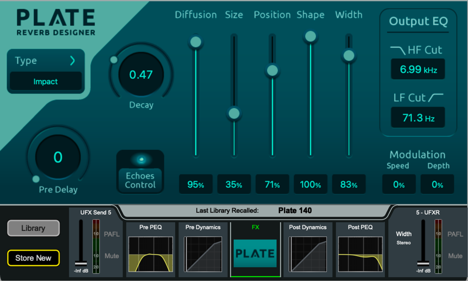
Plate Reverb Designer
Straightforward, high quality emulation of Plate style reverbs.
Type selects a model of Plate Reverb with different tonal character and transient response.
Plate types:
- Chrome - Vintage “chrome” plate, medium to large with brighter resonance.
- Steel - Vintage Steel plate, some dark resonances.
- Bright - Overly bright medium sized.
- Dark - Overly dark large sized plate with low mid resonances.
- Dark Vox - Large sized Dark plate optimised for vocal intelligibility.
- XL plate - Large ethereal plate with a strong initial attack.
- Vocal Focus - A gritty dense plate designed to cut through a mix.
- Small Plate - Short metallic plate.
- Ambience - Very small ambient plate designed to add air.
- Classic - Classic artificial plate model, medium sized.
- Impact - Strong early dense plate which can bring focus to instruments.
Pre Delay sets the Delay of the Dry signal entering the Reverb Engine (0-170ms).
Decay sets the total Decay time for the Reverb Engine (0.1s – 10s)
The Output EQ offers a quick and easy way to control the output EQ of the Reverb engine. This is in addition to the PEQ offered within the RackUltra FX channel strip.
Diffusion sets the Diffusion applied to the Input to the Reverb Engine. High Diffusion values will cause lush highly complex Reverb patterns, whilst Low Diffusion values will improve intelligibility.
Size allows for fine adjustment of the Plate Size as selected by the Type. As this is a fine adjustment, it should be noted that some Types set to “10” will be smaller than other Types set to “10”.
Position is a balance control between the Early and Late Reflection engines. A very low Position value will reduce the level of the Late Reflections and will sound very “immediate” in the mix, whilst a very high Position value will sound further away, with less focus on early reflections.
The Shape influences the build up of reflections within the Plate. With a lower Shape value reducing the density and improving intelligibility, or a larger Shape value increasing density for a “thicker” reverb tone.
Width allows for simple Stereo Width control ranging from 100% full stereo down to 0% Mono Summing of the Output signal.
Modulation can be applied to both the Early and Late Engine to provide chorusing and additional density.
Echoes Control opens a pop up window for control of 6 individually configurable Echoes. 3 Left (Blue) and 3 Right (Green). Each can have a discreet Gain value (-40db - +10dB), position in time (0 – 200ms) and can be turned On or Off.
Additionally the entire Echo engine can be switched In or Out using the control in the top right of the window.
Return to the main Plate Reverb Designer window by pressing the “X” in the top right hand corner of the Pop Up.
Vocal Shifter
Advanced Vocal Pitch Shifting with formant correction and modification.
Vocal Shifter uses voice detection to correct or manipulate the formant of the human voice across a range of shifted pitches. The RackUltra FX unit is split into controls for the Left and Right side of the Stereo FX send. Each side is otherwise identical and can be linked using the link control in the centre if desired.
Semitone shifts the pitch up or down by 12 semitones.
Formant changes the tone of the voice, a lower Formant setting ‘ages’ the voice as if coming from deeper within the throat, whilst a higher Formant setting “de-ages” the voice as if coming from higher in the throat. With the formant control set to 0, the Formant is corrected for the selected Pitch shift value. You can adjust the formant up or down from the corrected value to manipulate the Formant of the voice.
Delay adds up to 80ms of delay to the output from the unit.
Gain attenuates the output level from 0dB to -40dB.
Precision when enabled allows fine control of all parameters in 0.1 increment steps (otherwise 1.0 increment steps).
Vocal Tuner
Low latency Vocal Pitch correction with minimal audible artefacts.
Global Key when enabled, Vocal Tuner will follow the Global Key of the console rather than the Key and Scale settings for the unit.
Key & Scale will pre define which notes are available to tune to, based on either the Major, or Minor scale for the selected Key. When in Chromatic mode, Vocal Tuner will always tune to the nearest note, regardless of the key.
Range will improve the performance of the pitch detection of the Vocal Tuner by focusing on a specified vocal range. The options are Default (no vocal range focus), Baritone (E2 to A4), Alto/Tenor (C3 to F5), and Soprano (A3 to C6).
Reference Pitch can be used to set the frequency in Hz of A4. For use in styles of music with alternative Reference Pitch.
Bypass sets the correction value to 0%, configurable as a Softkey, Action or via MIDI control. To avoid tuning when not required.
Correction limits the Tuner correction, when used in conjunction with the Retune and Transition speed, can be used to create a more (or less) natural sounding Pitch Correction.
Retune sets the speed at which Vocal Tuner should correct to the correct note.
After Vocal tuner detects a change in the note being sung, Transition controls how soon to begin correcting the note.
Very fast Retune and Transition speeds will sound “robotic” and “choppy” whilst slower speeds will sound more natural but may never finish correcting the pitch before the next note.
Tracking is an internal threshold of the pitch detection circuit. Turning this parameter down will decrease the sensitivity of pitch detection, blocking background sound from being re-tuned.
The Keyboard shows the “legal” and “illegal” notes for the current Key and Scale. These can be further customised by touching each note. There are five possible options for each note.
Blank – This note is valid and will be both corrected and corrected into.
– – This note is invalid, if detected any notes sung here will be corrected up or down to the nearest valid note.
← – This note is invalid, if detected any notes sung here will be corrected down to the nearest valid note.
→ – This note is invalid, if detected any notes sung here will be corrected up to the nearest valid note.
× – This note is valid, however any notes detected here will not be corrected.
MIDI can be used via MIDI control to remotely trigger this FX unit. Sending a Note On message will ‘snap’ Vocal Tuner to a specific note, as if all other notes on the keyboard were set to “Invalid”. Sending a Note Off message will release this “snap”.
Other parameters can be controlled via MIDI by choosing a CC message from the “Show Routing” menu followed by “MIDI Setup”. These are:
- Retune
- Transition
- Correction
- Key
- Scale
- Bypass
🛈 For further information please refer to the dLive MIDI over TCP/IP Protocol document at www.allen-heath.com.
Vocal Gridder
Vocal Tune with fast pitch detection for hard and fast correction.
Global Key when enabled, Vocal Gridder will follow the Global Key of the console rather than the Key and Scale settings for the unit.
Key & Scale will pre define which notes are available to tune to, based on either the Major, or Minor scale for the selected Key. When in Chromatic mode, Vocal Tuner will always tune to the nearest note, regardless of the key.
Bypass stops Gridder from applying Pitch Correction, configurable as a Softkey, Action or via MIDI control. To avoid tuning when not required.
Reference Pitch can be used to set the frequency in hz of A4. For use in styles of music with alternative Reference Pitch.
Time Tolerance sets how long Vocal Gridder should tune to the current note before tuning to the next note.
Pitch Tolerance sets how far from the current note the Vocal should be allowed to drift before correcting to the next note.
After Vocal tuner detects a change in the note being sung, Transition controls how soon to begin correcting the note.
Very fast Retune and Transition speeds will sound “robotic” and “choppy” whilst slower speeds will sound more natural but may never finish correcting the pitch before the next note.
The Keyboard shows the “legal” and “illegal” notes for the current Key and Scale. These can be further customised by touching each note. There are five possible options for each note.
Blank – This note is valid and will be both corrected and corrected into.
– – This note is invalid, if detected any notes sung here will be corrected up or down to the nearest valid note.
← – This note is invalid, if detected any notes sung here will be corrected down to the nearest valid note.
→ – This note is invalid, if detected any notes sung here will be corrected up to the nearest valid note.
× – This note is valid, however any notes detected here will not be corrected.
MIDI can be used via MIDI control to remotely trigger this FX unit. Parameters can be controlled via MIDI by choosing a CC message from the “Show Routing” menu followed by “MIDI Setup”. These are:
- Speed
- Time Tolerance
- Key
- Scale
- Bypass
🛈 For further information please refer to the dLive MIDI over TCP/IP Protocol document at www.allen-heath.com.
Dual AutoKey Harmoniser
2 voice vocal harmoniser with sidechain Auto Key detection.
With Manual key enabled a Key and Scale can be chosen by touching the “Key” or “Scale” display.
With Global key enabled the unit will follow the Global key and scale of the console.
With AutoKey enabled the unit will detect the Key from a polyphonic source such as a piano or guitar. The key detection Source is configured by touching “Show Routing” and setting the External Side Chain Source.
The confidence meter will increase over time as the unit becomes more certain of the key. Once the key has been determined this can then be copied to the Manual key if desired.
This can also be used to set the Global Key automatically, if the “Copy Key to Manual” button is touched whilst the Harmoniser is in “Global key”.
The two voices of harmony have identical controls and can be enabled and disabled individually.
Each voice has the following controls:
Interval sets the Internal from the source voice the Harmony should be placed. These can be set from -8 (or one Octave down) to +8 (or one Octave up).
Formant control can be used to either corrected (Formant 0) or from -12 to +12 to modify the formant of each voice.
Gain sets the amount of attenuation for the individual voice from 0dB to -40dB.
Pan sets the relative Left/Right position of the individual voice.
The additional controls effect the entire unit.
Reverb uses the included Plate, without using an additional RackUltra FX slot if not required.
Chorus provides a simple Chorusing affect to the Harmonised voices.
Pitch Variation shifts the harmonised voices up and down slightly to recreate the natural sounds of a group of people singing together. This can be used in conjunction with Time Variation to control how natural (or not) the Harmonies sound.
Time Variation randomises the start and end time of each voice, can be used in conjunction with Pitch Variation to control now natural (or not) the Harmonies sound.
Auto Expand controls the depth of the Voice Detection expander, useful for tuning the Harmoniser to work with varying amounts of stage bleed.
MIDI can be used via MIDI control to remotely trigger this FX unit. Parameters can be controlled via MIDI by choosing a CC message from the “Show Routing” menu followed by “MIDI Setup”. These are:
- Key
- Scale
🛈 For further information please refer to the dLive MIDI over TCP/IP Protocol document at www.allen-heath.com.
Quad Voice Harmoniser
4 voice vocal harmoniser.
Key/Scale selects a Key and Scale can be chosen by touching the “Key” or “Scale” display.
With Global key enabled Quad Voice Harmoniser will follow the Global key and scale of the console.
Each voice has the following controls;
Interval sets the Interval from the source voice the Harmony should be placed. These can be set from -8 (or one Octave down) to +8 (or one Octave up).
Formant control can be used to either corrected (Formant 0) or from -12 to +12 to modify the formant of each voice.
Gain sets the amount of attenuation for the individual voice from 0dB to -40dB.
Pan sets the relative Left/Right position of the individual voice.
The additional controls effect the entire unit.
Reverb uses the included Plate, without using an additional RackUltra FX slot if not required.
Chorus provides a simple Chorusing affect to the Harmonised voices.
Pitch Variation shifts the harmonised voices up and down slightly to recreate the natural sounds of a group of people singing together. This can be used in conjunction with Time Variation to control how natural (or not) the Harmonies sound.
Time Variation randomises the start and end time of each voice, can be used in conjunction with Pitch Variation to control now natural (or not) the Harmonies sound.
Auto Expand controls the depth of the Voice Detection expander, useful for tuning the Harmoniser to work with varying amounts of stage bleed.
MIDI can be used via MIDI control to remotely trigger this FX unit. Parameters can be controlled via MIDI by choosing a CC message from the “Show Routing” menu followed by “MIDI Setup”. These are:
- Key
- Scale
🛈 For further information please refer to the dLive MIDI over TCP/IP Protocol document at www.allen-heath.com.
MIDI Harmoniser
4 voices of MIDI controlled Harmony.
Monophonic Mode when enabled the unit accepts a single MIDI note.
Glide sets the speed at which the Harmoniser will transition from one MIDI note to another.
Polyphonic Mode allows up to 4 voices to be played at the same time.
Width controls the stereo spread of the 4 voices of harmony.
In all modes you have the following additional controls.
Reverb uses the included Plate, without using an additional RackUltra FX slot if not required.
Chorus provides a simple Chorusing affect to the Harmonised voices.
Pitch Variation shifts the harmonised voices up and down slightly to recreate the natural sounds of a group of people singing together.
Use Velocity can be used to follow the velocity value of the MIDI note. The higher the velocity value the louder the harmonised voice will be, a smaller velocity value will result in a quieter harmonised voice.
Amp+Cab Distortion
Amplifier modelling and cab simulation.
Amp Type loads the Amplifier Model into the unit. The Amplifier models available are:
Deluxe The classic Californian guitar amplifier powered by 6V6 valves and renowned for its mid-scooped clean and edge-of-breakup tones.
VX30 Legendary copper panelled EL84-powered British amp renowned for its chime and jangle, made famous by the British Invasion of the 1960s.
MPlex The iconic gold-panelled rock amplifier of the 70s, 80s and beyond, capable of smooth overdrive through to high-gain.
BDS1 The orange distortion pedal from 1978 that was pivotal in the harder sounds of rock during the 1980s and 1990s thanks to its hard attack and smooth sustain.
BassVT The definitive all-valve bass amplifier, capable of clean through to overdriven tones, relied on by touring and session musicians since 1969.
Cabinet Simulator loads the cabinet and driver model. The models available are:
FDR 1x12 1x12” open-back Californian combo with American speaker.
FV 2x10 2x10” open-back Californian combo with Italian speakers.
VX 2x12 2x12” copper-panel British combo with AlNiCo speakers.
Cel 1x12 1x12” AlNiCo driver in a closed-back cabinet.
MCel 4x12 4x12” closed-back cabinet with classic UK speakers.
VCel 2x12 2x12” open-back cabinet with vintage UK speaker.
Bass 8x10A First of two flavours of 8x10” US bass cabinets.
Bass 8x10B Second of two flavours of 8x10” US bass cabinets.
Bass 1x15 1x15” Classic closed-back US bass cabinet.
You can also choose to select “None” to run the unit without emulating the effect of the speaker driver and cabinet.
Gain drives signal level into the model.
Output drives signal level out of the model, a low output level can be used in conjunction with a very high gain level to create significant distortion at lower volume levels.
Thicken slightly alters distortion parameters on the Left and Right side of the unit to simulate a second cab. Additionally adds subtle chorus to widen the sound stage.
EQ controls are the same for all models for ease of use.
Saturator
Analog Saturation emulation with EQ controls.
Mode selects the model, there are 5 available.
Mode A Triode Valve Preamp Model. Rich in second and third harmonics. This model is the cleanest available on Saturator with low harmonic distortion and a gentle roll-off on frequencies over 10kHz. (Least aggressive).
Mode B Pentode Valve Preamp Model. Rich in second, third and higher order harmonics. Minimal high frequency roll off.
Mode C Late 1960s germanium transistor based Preamp Model. With characteristic roll off on frequencies over 12kHz.
Mode D Channel strip model with vintage bipolar transistor and small signal transistor. Wide high frequency lift at around 8kHz and for air and clarity.
Mode E Tape Drive Preamp model. Accurate low and low-mid attenuation with extremely aggressive levels of distortion when Gain is turned up to maximum. (Most aggressive).
The Bias control simulates a DC offset on the input audio. This can be used to create distortion at low volumes.
The PAD control reduces the Input level to the unit by -30dB for a much more subtle effect. With PAD enabled, a 30dB boost is added at the output stage to maintain relative volume.
Tilt provides a combined LF and HF shelf control with continuous control from “Full Anticlockwise” 20dB high frequency reduction shelved from 3k5Hz, to “Full Clockwise” 20dB low frequency reduction shelved from 100hz.
LF Cut 12dB LPF. 20Hz to 1kHz
LF Punch Adds a low frequency boost around the LF Cut frequency.
HF Cut switchable slope 6/12dB HPF. 1kHz to 24kHz.
Level make-up output gain level -40dB to +10dB.
Rhythm Delay
Pattern Delay with extensive customisation.
Rhythm Delay uses both BPM, Bar and Beat information to create a Delay Unit capable of positioning repeats precisely within a bar of variable length.
Simple Mode
Tempo
BPM shown here can be tapped in via a Softkey on either a Global basis syncing with all of the other Global tap devices on the console. Or individually.
Dotted and Triplet controls set the note type, whilst having neither selected defaults to a normal node.
Rhythm
Interval sets the time between each repeat as a fraction of the bar length.
Number of Repeats – Sets the number of Repeats per bar.
Each repeat will be added from the start of the bar spaced out by the Interval value.
Shape
Amplitude Shape controls the amplitude of the repeats, whilst the % control affects how much this should affect the amplitude of the repeats.
Auto Pan sets the depth of the Auto Pan. The speed of the Auto Pan is tied to ¼ note of the current BPM.
Feedback
Feedback Filters can be used to shape the tone of audio going through the feedback path.
LF Cut – Selectable as a 3dB shelf, 6 or 12dB High Pass Filter.
Resonant – Variable width bell curve filter.
HF Cut – Selectable as a 3dB shelf, 6 or 12dB Low Pass Filter.
Feedback controls the gain of the Feedback path. Can be used with positive values to have a delay get louder with each pass if desired.
Drive adds Saturation to the Feedback Path.
If a parameter has been adjusted in Advanced Mode, this is shown in Simple Mode with a red notice. This can be cleared by adjusting the value in Simple Mode, clearing the Advanced Mode setting.
Advanced Mode
Tempo – As per Simple Mode above.
Feedback Filters – As per Simple Mode above.
Amplitude Shape – Offers all Simple Mode options with the addition of “Custom Mode”.
The main Grid of Rhythm Delay in Advanced Mode shows all the repeats. The currently selected repeat is highlighted in blue, and it’s individual controls shown on the right-hand side.
Add a new repeat by touching Add or Remove a repeat by first selecting it, then touching Remove from the right-hand side.
Repeats may be positioned within the bar by touching and dragging them, or by using the Main Screen encoder.
The Height of a repeat indicates the Gain of the repeat. If the Amplitude Shape is set to Custom this may be adjusted by dragging the repeat on the screen, or by adjusting the Gain value on the right hand side.
The Pan of each repeat may be adjusted by it’s Pan control on the right hand side.
When not selected, each repeat will show a solid White colour to indicate it is panned left, a solid Red colour to indicate it is panned right, or a yellow to indicate it is perfectly centred.
Turning Dry Repeat on will feed the input signal directly to the output of the Delay unit, precisely 1 bar after it is received. This is shown in Green.
The Bar Length can be adjusted for alternative time signatures.
Pattern Tap ARM clears the Repeat Grid to allow a pattern to be tapped on the screen in time with the music.