PACKED ITEMS
Xone:K3 MIDI Controller
1m type C - C USB cable
To connect the Xone:K3 to your computer or host device.
QR Card
Follow the QR link access the latest resources for the unit.
Safety and Regulatory Information Booklet
Contains important safety information and should be read before use.
PRODUCT OVERVIEW
The Xone:K3 is a customisable MIDI controller designed to work with any software application that supports MIDI, including for DJ and audio performance as well as many popular video, lighting and other multimedia applications.
The main features of the Xone:K3 are:
- 52 hardware controls providing up to 174 MIDI control commands across three layers
- 30 tactile soft switches. 4 faders. 6 push encoders & 12 rotary potentiometers.
- Full MIDI customisation of individual controls
- Customisable Latching Layers system
- Backlit switches with individual RGB LED illumination
- USB bus Powered
- X:LINK In/Out
- Die cast chassis with steel front panel and 'nutted' pots
MIDI Controls
The unit can be used with each control assigned to only one parameter (Latching Layers Off) or set to use a ‘Latching Layers Mode’ with 3 layers available. All controls can be individually configured for each layer using the Xone Controller Editor application.
USB-C
Xone:K3 features a USB-C port for connecting to your host system. The Xone:K3 is a class compliant MIDI device and can be used with a Windows PC computer, macOS computer, iOS device (iPad/iPhone). The USB port is designed to support star topology and external USB hubs for multiple Xone:K3 connections, where each controller connects independently to the USB host.
X:LINK
X:LINK allows the Xone:K3 to be connected any X:LINK enabled Xone mixer or legacy Xone:K series device using a standard CAT5 network cable with RJ45 connections.
This connection powers the unit and passes MIDI messaging to/from the Xone:K3. Multiple K series units can also be cascaded using X:LINK. Please refer to the USB and X:LINK application diagrams later in this guide for more details and examples.
ⓘ The Xone:K3 does not supply power to the X:LINK connection when it is powered via USB.
Xone Controller Editor software
Xone:K3 has editor software, available to download for free from the Resources section of the Allen&Heath website. This is used to customise the MIDI messaging, change the LED feedback behaviour and colours and Save/Load custom Xone:K3 hardware mapping.
REAR PANEL CONNECTORS
USB C Port
Socket for connecting the Xone:K3 to the USB host (Windows PC / macOS / iOS / mobile device)
X:LINK IN Socket
This RJ45 socket is used if the K3 is being powered via X:LINK. This will then supply power to and receive data from a downstream K series device.
X:LINK OUT Socket
This RJ45 socket for proprietary connection to an X:LINK enabled Xone mixer, a legacy Xone:K-series device or another Xone:K3 that is respectively downstream on X:LINK.
USB C CONNECTION
Xone:K3 features a type C USB port for connecting to your host system i.e. PC computer, macOS computer, iOS device (iPad/iPhone) or any other device that supports Class Compliant MIDI devices.
The USB port is designed to support star topology either directly or via external USB hubs for multiple Xone:K3 connections, where each controller connects independently to the USB host.
ⓘ When the Xone:K3 is being powered by USB, X:LINK will not supply power.
The examples below show how the Xone:K3 should be connected to a host.
X:LINK PROTOCOL
The X:LINK protocol is a proprietary Allen and Heath protocol for connection between X:LINK enabled products.
An X:LINK host (Xone Series mixer, Xone:K1, or Xone:K2) provides power and MIDI data transfer between units.
ⓘ X:LINK does not include the transfer of any audio when using a Xone:K2.
Use the provided RJ45 cable to link the OUT connection on one unit to the IN connection of the other. The same connection method can be applied to Xone:K1, substituting the Xone:K2s in any of the examples below.
Both Xone:K1 & Xone:K2 deliver power over X:LINK when connected via USB. Therefore, when using either of these with Xone:K3, the predecessor models must always be connected to the host.
In order for the units to work independently of each other when connected via X:LINK, it is recommended to use the Global MIDI channel setting to set a different global MIDI channel for each controller, as well as set any customised controls to use the Global MIDI channel.
SOFTWARE CONNECTION
The Xone:K3 is class compliant and enumerates as a MIDI device on any host device that supports class compliant USB MIDI devices, including Windows, MacOS, iOS and most Android devices.
Connecting to a host via USB C
MacOS/Windows
Xone:K3 is a class compliant USB MIDI device, therefore no drivers are required for use with any supported host. Simply connect Xone:K3 to your computer and it will display respectively as shown:
The Xone:K3 will then show up as a possible MIDI input and output device in any software which supports external MIDI devices.
iPad and other tablets or mobile devices
Xone:K3 can be connected to an Apple iPad. With older iPads without a USB-C connection, an Apple Camera Connection Kit (not included) is required. For connection to newer iPads and other devices with a USB-C connection, it is still recommended that a dongle or adaptor with power delivery is used to ensure that power is continually supplied to the iPad.
The device will display the Xone:K3 as an input and output option within any app or software which supports MIDI. Below is a screen capture from AUM on iOS.
Connecting multiple K3 devices to a host
When connecting more than one Xone:K3 unit, each device connected via USB can be independently identified and addessed by the host system and software. This can be achieved either through the available USB ports on the host, or via a USB hub, creating a star topology.
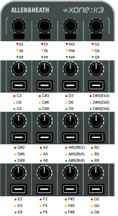
MIDI CONTROLS
Rotary Encoders
By default, turning an encoder produces MIDI CC (continuous controller) messages with a unique controller number in two’s compliment binary encoding.
These encoders also feature a built in momentary push switch. By default, pressing down on the encoder knob activates the switch and sends a “Note On” MIDI message, releasing the switch sends a corresponding “Note Off” message.
The window below the top row of encoders displays the state of the encoder switch in the same manner as the button switches.
Rotary Potentiometers
These controls are standard potentiometers with end stops. Turning a pot from left to right will send MIDI messages with a unique CC number and a control value from 0 to 127.
Pot Switches
Each rotary potentiometer has a back-lit button switch with RGB colour illumination below it. By default, pressing a button sends a “Note On” MIDI message, activating the switch. Releasing the button sends a corresponding “Note Off” message to deactivate the switch.
Faders
Moving a linear fader will send a MIDI message with a unique CC number and a control value from 0 to 127.
Switch Matrix
The switch matrix consists of 16 back-lit RGB-colour button switches.
Default actions for Switch Matrix buttons are the same as for Pot Switches.
LAYER Button
The Layer button is completely user assignable but can also function as an embedded layer button which cycles through the 3 unit layers.
SHIFT Button
The SHIFT button is completely user assignable as a MIDI control, typically used to function as dedicated button to switch (SHIFT) between different states in the software host.
ⓘ The SHIFT button switch and bottom-right encoder push-switch are also used to navigate the controller hardware setup options.
POWER ON SETUP Modes
The Xone:K3 has a setup mode which can be entered before starting your session. There are three parameters that can be entered, configured and recalled; the device global MIDI channel, Latching Layers and the UNIT MAPS.
To enter the setup mode, press and hold down the bottom-right encoder [1] labelled 'POWER ON SETUP', then power up the unit by connecting the USB-C cable, or RJ45 lead if powering from X-LINK. The SHIFT switch LED will flash amber then illuminate solid and the top left switch matrix button will illuminate green to indicate that the K3 has entered setup mode as shown:
Rotating the 'POWER ON SETUP' encoder will scroll between the three parameters that can be adjusted, with the first three switches illuminating to show which is currently selected.
Switch 1 - Change the Global MIDI Channel Number
Switch 2 - Change the Latching Layers Mode
Switch 3 - Recall a Map which has been stored on the unit via the Xone Controller Editor app.
| 1 MIDI CHANNEL NUMBER | 2 LATCHING LAYERS | 3 UNIT MAPS |
To make changes to the parameter, press the encoder [1] again, and configure as detailed below.
To exit setup mode, press the SHIFT switch and the unit will restart.
GLOBAL MIDI CHANNEL NUMBER
The Global MIDI Channel affects all controls in the default Map, and any controls which have been set to use the Global MIDI Channel in a user Map.
By default the controller’s Global MIDI Channel number is set to 15 to prevent control interaction with Xone Series mixer interfaces which default to channel 16.
The Global MIDI channel number on your Xone:K3 can be changed on the device by entering POWER ON SETUP mode.
Setup Mode
To enter the setup mode, press and hold down the bottom-right encoder [1] then power up the unit by plugging the USB cable to your PC/Mac, (or RJ45 lead if powered from X-LINK). The SHIFT switch LED will flash amber then illuminate solid and the top left switch matrix button will illuminate to indicate that the Xone:K3 has entered setup mode.
The first illuminated switch presents the MIDI channel options, used to configure the controller’s global MIDI channel. The display will default as below.
Press the ‘SEL’ encoder [1] to display the current MIDI channel number; see below.
Setting the Global MIDI Channel Number
The channel number is represented by the number of illuminated switch buttons. This example shows MIDI Channel 14.
Xone:K3 defaults to MIDI channel 15.
To change the MIDI Channel number, rotate the Setup encoder.
When the desired MIDI Channel Number has been chosen, press the ‘SEL’ Encoder [1] to store it and return to the setup mode.
Press the amber (SHIFT) switch to exit setup mode and the unit will restart.
LATCHING LAYERS
Latching Layers’ provide embedded layer control via the ‘LAYER’ button on the Xone:K3.
If Latching Layers are on, the LAYER switch is used to toggle between three available layers (by default RED, AMBER then GREEN).
From this, by default, if the LAYER switch is RED, any switch used on this layer will illuminate RED
If the layer switch is AMBER, then any switch used on this layer will illuminate AMBER etc.
Options for the Latching Layers system on your Xone:K3 are accessed in setup mode.
Setup Mode
To enter setup mode, press and hold down the bottom-right encoder [1] then power up by plugging the USB
cable to your PC/Mac, (or RJ45 lead if powered from X-LINK). The SHIFT switch LED will flash amber then
illuminate solid and the top left switch matrix button will illuminate to indicate that the Xone:K3 has entered setup mode.
Rotate the setup encoder [1] until the second top row matrix switch LED illuminates as shown:
Press the ‘SEL’ encoder [1] to display which components are attached to the latching layers.
Latching Layer Options
Use the rotary action of the Setup encoder to select between the Latching Layer options.
The Latching Layer states shown above are described as follows:
- LATCHING LAYERS OFF - In this state, Latching Layers are disabled and the ‘Layer’ button is available for general user configuration.
- SWITCH MATRIX - In this state, the 16 switches in the Switch Matrix are linked to Latching Layers.
- POT SWITCHES - In this state, the switches under the pots and the top row encoder switches are linked to Latching layers.
- ALL SWITCHES - In this state, all switches on the surface are linked to Latching Layers.
- ALL CONTROLS - In this state, all controls on the surface are linked to Latching Layers. The faders and pots have an embedded soft pick up algorithm to provide seamless integration across layers.
If Latching Layers are ‘on’ (states [2], [3], [4] and [5]), the LAYER switch is active to toggle between the three layers.
Once the desired controls are linked to the Latching Layers, press the setup encoder to store and return to the setup mode.
Press the amber (SHIFT) switch to exit setup mode and the unit will restart.
When controls have been added to the latching layers system, by default the LAYER switch will be illuminated RED (layer 1) once the unit has exited setup mode. The LED colour of the LAYER switch can be customised for each layer via the Xone Controller Editor application.
UNIT MAPS
A default Factory Map is pre-installed in the Xone:K3 and is loaded by default when the device is first powered on.
Controls and LED feedback in this UNIT MAP operate in the same way as a Xone:K2 functions. This is for ease of integration with pre-existing Xone:K2 setups and software that supports Xone:K2 or Xone:K1 integration.
Up to three customised unit maps can also be saved locally to 'slots' on the Xone:K3 device using the Xone
Controller Editor application. Any UNIT MAP can also be loaded from the Xone Controller Editor application, or recalled from the Xone:K3 during the POWER ON SETUP process.
ⓘ The selected UNIT MAP is recalled on subsequent connections until a different UNIT MAP is recalled by the POWER ON SETUP process, or loaded using the Xone Controller Editor application.
Setup Mode
To enter the setup mode, press and hold down the encoder [1] then power ON by plugging the USB cable to your PC/Mac, (or RJ45 lead if powering from X-LINK). The SHIFT switch LED will flash amber then illuminate solid and the top left switch matrix button will illuminate to indicate that the Xone:K3 has entered setup mode.
Rotate the setup encoder [1] until the third top row matrix switch LED illuminates (as shown below).
Recall a UNIT MAP
When user Maps are saved to the controller, one of the remaining four top row switch matrix buttons corresponding to the unit map slot chosen in the Xone Controller Editor application. illuminates BLUE to indicate a custom map is stored.
The currently selected map is displayed by an AMBER switch LED
Use the rotary action of the Setup encoder to select between the available UNIT MAPS on the device. The active unit map can also be loaded from the Xone Controller Editor application.
Factory Map (1) - In this state, the controller will work in the same way as a Xone:K2. All MIDI values and LED colours match the Xone:K2 settings so you can easily migrate software assigned to a Xone:K2, or a Xone:K1 to your new Xone:K3
Map 2 - User Map - Must be saved in the Xone Controller Editor software’s ‘UNIT MAPS’ to be available on hardware
Map 3 - User Map - Must be saved in the Xone Controller Editor software’s ‘UNIT MAPS’ to be available on hardware
Map 4 - User Map - Must be saved in the Xone Controller Editor software’s ‘UNIT MAPS’ to be available on hardware
Once the required unit map has been selected, press the ‘SEL’ encoder to load the configuration and return to the setup mode. Press the SHIFT button to exit setup mode and the unit will restart running the selected user Map.
MIDI IMPLEMENTATION DEFAULT:
SEND
MIDI IMPLEMENTATION DEFAULT:
RETURN
MIDI CONVERSION TABLE
| DEC | Note | HEX | DEC | Note | HEX | DEC | Note | HEX | DEC | Note | HEX | |||
| 0 | C-1 | 00 | 32 | G#1 | 20 | 64 | E4 | 40 | 96 | C7 | 60 | |||
| 1 | C#-1 | 01 | 33 | A1 | 21 | 65 | F4 | 41 | 97 | C#7 | 61 | |||
| 2 | D-1 | 02 | 34 | A#1 | 22 | 66 | F#4 | 42 | 98 | D7 | 62 | |||
| 3 | D#-1 | 03 | 35 | B1 | 23 | 67 | G4 | 43 | 99 | D#7 | 63 | |||
| 4 | E-1 | 04 | 36 | C2 | 24 | 68 | G#4 | 44 | 100 | E7 | 64 | |||
| 5 | F-1 | 05 | 37 | C#2 | 25 | 69 | A4 | 45 | 101 | F7 | 65 | |||
| 6 | F#-1 | 06 | 38 | D2 | 26 | 70 | A#4 | 46 | 102 | F#7 | 66 | |||
| 7 | G-1 | 07 | 39 | D#2 | 27 | 71 | B4 | 47 | 103 | G7 | 67 | |||
| 8 | G#-1 | 08 | 40 | E2 | 28 | 72 | C5 | 48 | 104 | G#7 | 68 | |||
| 9 | A-1 | 09 | 41 | F2 | 29 | 73 | C#5 | 49 | 105 | A7 | 69 | |||
| 10 | A#-1 | 0A | 42 | F#2 | 2A | 74 | D5 | 4A | 106 | A#7 | 6A | |||
| 11 | B-1 | 0B | 43 | G2 | 2B | 75 | D#5 | 4B | 107 | B7 | 6B | |||
| 12 | C0 | 0C | 44 | G#2 | 2C | 76 | E5 | 4C | 108 | C8 | 6C | |||
| 13 | C#0 | 0D | 45 | A2 | 2D | 77 | F5 | 4D | 109 | C#8 | 6D | |||
| 14 | D0 | 0E | 46 | A#2 | 2E | 78 | F#5 | 4E | 110 | D8 | 6E | |||
| 15 | D#0 | 0F | 47 | B2 | 2F | 79 | G5 | 4F | 111 | D#8 | 6F | |||
| 16 | E0 | 10 | 48 | C3 | 30 | 80 | G#5 | 50 | 112 | E8 | 70 | |||
| 17 | F0 | 11 | 49 | C#3 | 31 | 81 | A5 | 51 | 113 | F8 | 71 | |||
| 18 | F#0 | 12 | 50 | D3 | 32 | 82 | A#5 | 52 | 114 | F#8 | 72 | |||
| 19 | G0 | 13 | 51 | D#3 | 33 | 83 | B5 | 53 | 115 | G8 | 73 | |||
| 20 | G#0 | 14 | 52 | E3 | 34 | 84 | C6 | 54 | 116 | G#8 | 74 | |||
| 21 | A0 | 15 | 53 | F3 | 35 | 85 | C#6 | 55 | 117 | A8 | 75 | |||
| 22 | A#0 | 16 | 54 | F#3 | 36 | 86 | D6 | 56 | 118 | A#8 | 76 | |||
| 23 | B0 | 17 | 55 | G3 | 37 | 87 | D#6 | 57 | 119 | B8 | 77 | |||
| 24 | C1 | 18 | 56 | G#3 | 38 | 88 | E6 | 58 | 120 | C9 | 78 | |||
| 25 | C#1 | 19 | 57 | A3 | 39 | 89 | F6 | 59 | 121 | C#9 | 79 | |||
| 26 | D1 | 1A | 58 | A#3 | 3A | 90 | F#6 | 5A | 122 | D9 | 7A | |||
| 27 | D#1 | 1B | 59 | B3 | 3B | 91 | G6 | 5B | 123 | D#9 | 7B | |||
| 28 | E1 | 1C | 60 | C4 | 3C | 92 | G#6 | 5C | 124 | E9 | 7C | |||
| 29 | F1 | 1D | 61 | C#4 | 3D | 93 | A6 | 5D | 125 | F9 | 7D | |||
| 30 | F#1 | 1E | 62 | D4 | 3E | 94 | A#6 | 5E | 126 | F#9 | 7E | |||
| 31 | G1 | 1F | 63 | D#4 | 3F | 95 | B6 | 5F | 127 | G9 | 7F |
SPECIFICATIONS
| Connectivity | ||
| USB | ||
| · Port | type USB-C |
power and data |
| · USB host | USB 2.0 |
Full Speed (12Mbps) |
| X:Link | ||
| · Port | type RJ45 x 2 |
IN + OUT Full-duplex ¦ Data only |
| X:LINK for power and data via other Xone products | ||
| Hardware Controls | ||
| · Potentiometers | 12 |
270° rotation |
| · Faders | 4 |
60mm linear faders |
| · Endless encoders | 6 |
inc. push switch |
| · Tactile switches | 30 |
with RGB LED feedback |
| · RGB LEDs | 34 |
16 colour palette |
| MIDI Controls | 174 Total |
|
| Defaults | QTY |
Range |
| · MIDI Channels | 16 |
1-16 |
| · Control Change – absolute | 16 |
0-127 |
| · Control Change – relative | 6 |
127/1 |
| · Note ON / Note OFF | 36 |
127/1 |
| Power Requirement | ||
| · USB host | 5V, 450mA max |
|
| Power Consumption | max, per device |
|
| · USB host | 450mA @ 5V = 2.25W |
|
| · XLINK host | 450mA @ 5V = 2.25W |
|
| Dimensions | ||
| Unpacked | ||
| · Height | 49.5mm |
2” |
| · Width | 135mm |
5.3” |
| · Depth | 358mm |
14.1” |
| Packed | ||
| · Height | 85mm |
3.4" |
| · Width | 190mm |
7.5" |
| · Depth | 445mm |
17.5" |
| Weight | ||
| Unpacked | 1.25kg |
2.2lbs |
| Packed | 1.6kg |
3.5lbs |
REGISTERING YOUR PRODUCT
Register your unit and sign up for the newsletter to stay informed on important news and updates.